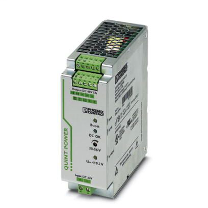
DC/DC converters - QUINT-PS/24DC/48DC/ 5 - 2320128
- Produttore:
- PHOENIX CONTACT
Primary-switched QUINT DC/DC converter for DIN rail mounting with SFB (Selective Fuse Breaking) Technology, input: 24 V DC, output: 48 V DC/5 A
Features
Reliable starting of difficult loads, thanks to the static POWER BOOST power reserve with up to 125% nominal current permanently
Preventive function monitoring indicates critical operating states before errors occur
Constant voltage: output voltage regenerated even at the end of long cables
Support conversion to various voltage levels
Electrical isolation: for setting up independent supply systems
BV
cULus Listed
EAC
cULus Recognized
LR
RINA
NK
IECEE CB Scheme
DNV GL
ABS
UL Listed
cUL Listed
UL Recognized
cUL Recognized
Specifications
| Depth | 125 mm |
|---|---|
| Height | 130 mm |
| Output Voltage | 48 V |
| Strip Length | 7 mm |
| Voltage | 10 V |
| Width | 48 mm |
Output data | |
| Nominal output voltage | 48 V DC ±1 % |
| Setting range of the output voltage (USet) | 30 V DC - 56 V DC (> 48 V DC, constant capacity restricted) |
| Nominal output current (IN) | 5 A (-25 °C - 60 °C) |
| POWER BOOST (IBoost) | 6.25 A (-25°C - 40°C permanent, UOUT = 48 V DC ) |
| Selective Fuse Breaking (ISFB) | 30 A (12 ms) |
| Derating | 60 °C - 70 °C (2.5%/K) |
| Connection in parallel | Yes, for redundancy and increased capacity |
| Connection in series | yes |
| Feedback voltage resistance | 60 V DC |
| Protection against overvoltage at the output (OVP) | < 60 V DC |
| Max. capacitive load | unlimited |
| Active current limitation | Approximately 7 A |
| Control deviation | < 1 % (change in load, static 10 % - 90 %) |
| Control deviation | < 2 % (change in load, dynamic 10 % - 90 %) |
| Control deviation | < 0.1 % (change in input voltage ±10 %) |
| Residual ripple | < 20 mVPP |
| Peak switching voltages nominal load | < 10 mVPP (20 MHz) |
| Maximum power dissipation in no-load condition | 5.2 W |
| Power loss nominal load max. | 21 W |
Conformance/approvals | |
| UL approvals | UL/C-UL listed UL 508 |
| UL approvals | UL/C-UL Recognized UL 60950-1 |
| UL approvals | UL ANSI/ISA-12.12.01 Class I, Division 2, Groups A, B, C, D (Hazardous Location) |
| Shipbuilding approval | DNV GL (EMC B) |
Environmental Product Compliance | |
| REACh SVHC | Lead 7439-92-1 |
| China RoHS | Environmentally Friendly Use Period = 25; |
| China RoHS | For details about hazardous substances go to tab 'Downloads', Category 'Manufacturer's declaration' |
Ambient conditions | |
| Degree of protection | IP20 |
| Ambient temperature (operation) | -25 °C - 70 °C (> 60 °C derating, 2.5 %/K, startup at -40°C type-tested) |
| Ambient temperature (start-up type tested) | -40 °C |
| Ambient temperature (storage/transport) | -40 °C - 85 °C |
| Max. permissible relative humidity (operation) | ≤ 95 % (at 25 °C, non-condensing) |
| Climatic class | 3K3 (in acc. with EN 60721) |
| Degree of pollution | 2 |
Standards | |
| EMC requirements for noise immunity | EN 61000-6-1 |
| EMC requirements for noise immunity | EN 61000-6-2 |
| EMC requirements for noise emission | EN 61000-6-3 |
| EMC requirements for noise emission | EN 61000-6-4 |
| Standard - Electrical safety | EN 60950-1/VDE 0805 (SELV) |
| Standard – Electronic equipment for use in electrical power installations and their assembly into electrical power installations | EN 50178/VDE 0160 (PELV) |
| Standard – Safety extra-low voltage | EN 60950-1 (SELV) |
| Standard – Safety extra-low voltage | EN 60204 (PELV) |
| Standard - Safe isolation | DIN VDE 0100-410 |
| Rail applications | EN 50121-4 |
Dimensions | |
| Width | 48 mm |
| Installation distance top/bottom (active) | 50 mm / 50 mm (≤ 70 °C) |
| Height | 130 mm |
| Depth | 125 mm |
| Width with alternative assembly | 122 mm |
| Height with alternative assembly | 130 mm |
| Depth with alternative assembly | 51 mm |
| Installation distance right/left | 0 mm / 0 mm (≤ 70 °C) |
| Installation distance left/right (active) | 15 mm / 15 mm (≤ 70 °C) |
| Installation distance top/bottom | 50 mm / 50 mm (≤ 70 °C) |
EMC data | |
| Electromagnetic HF field | EN 61000-4-3 |
| Frequency range | 80 MHz - 1 GHz |
| Frequency range | 1.4 GHz - 2 GHz |
| Test field strength | 10 V/m |
| Frequency range | 2 GHz - 3 GHz |
| Fast transients (burst) | EN 61000-4-4 |
| Input | 2 kV (Test Level 3 - asymmetrical) |
| Output | 2 kV (Test Level 3 - asymmetrical) |
| Signal | 2 kV (Test Level 4 - asymmetrical) |
| Surge voltage load (surge) | EN 61000-4-5 |
| Input | 1 kV (Test Level 2 - symmetrical) |
| Output | 1 kV (Test Level 2 - symmetrical) |
| Signal | 1 kV (Test Level 2 - asymmetrical) |
| Comments | Criterion A |
| I/O/S | asymmetrical |
| Frequency range | 0.15 MHz - 80 MHz |
| Voltage | 10 V (Test Level 3) |
| Criterion A | Normal operating behavior within the specified limits. |
| Criterion B | Temporary impairment to operational behavior that is corrected by the device itself. |
| Electromagnetic compatibility | Conformance with EMC Directive 2014/30/EU |
| Electrostatic discharge | EN 61000-4-2 |
| Contact discharge | 8 kV (Test Level 4) |
| Discharge in air | 15 kV (Test Level 4) |
Connection data, input | |
| Connection method | Pluggable screw connection |
| Conductor cross section solid min. | 0.2 mm² |
| Conductor cross section solid max. | 2.5 mm² |
| Conductor cross section flexible min. | 0.2 mm² |
| Conductor cross section flexible max. | 2.5 mm² |
| Conductor cross section AWG min. | 24 |
| Conductor cross section AWG max. | 12 |
| Stripping length | 8 mm |
| Screw thread | M3 |
Connection data, output | |
| Connection method | Pluggable screw connection |
| Conductor cross section solid min. | 0.2 mm² |
| Conductor cross section solid max. | 2.5 mm² |
| Conductor cross section flexible min. | 0.2 mm² |
| Conductor cross section flexible max. | 2.5 mm² |
| Conductor cross section AWG min. | 24 |
| Conductor cross section AWG max. | 12 |
| Stripping length | 7 mm |
| Screw thread | M3 |
Input data | |
| Nominal input voltage range | 24 V DC |
| Input voltage range | 18 V DC - 32 V DC |
| Extended input voltage range in operation | 14 V DC - 18 V DC (Derating) |
| Current consumption | 14 A (24 V, IBOOST) |
| Inrush current | < 15 A (typical) |
| Mains buffering time | > 12 ms (24 V DC) |
| Input fuse | 25 A (internal (device protection)) |
| Type of protection | Transient surge protection |
| Protective circuit/component | Varistor |
Connection data for signaling | |
| Conductor cross section solid min. | 0.2 mm² |
| Conductor cross section solid max. | 2.5 mm² |
| Conductor cross section flexible min. | 0.2 mm² |
| Conductor cross section flexible max. | 2.5 mm² |
| Conductor cross section AWG min. | 24 |
| Conductor cross section AWG max. | 12 |
| Screw thread | M3 |


